LXR

Descent Manual

Descent

Controls

  1. Decay Rate
    40ms to 5sec (EXP)
    80ms to 25sec (LIN)
    Adjustable via trimmer on the back

  2. Signal LED
    Visual representation of the decay signal

  3. Trigger/Gate Switch
    UP: Decay is triggered immediately by a rising edge on the gate jack
    Down: Envelope stays high while the GATE signal is high. The decay phase starts when the gate signal goes low.

  4. Gate signal input
    Channel 1 jack is normalized to channel 2

  5. CV inputs for the decay rate (5V)

  6. Output
    Envelope signal output (0 to 8V)

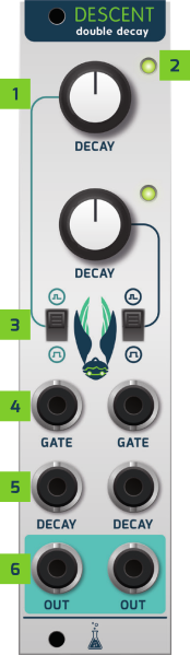
Decay behaviour settings

The shape of the envelope curve can be adjusted with 2 trimmers on the back.
The times given in the table are just approximate values, since due to component tolerance they may vary a bit.
If you feel the times should be longer, you can increase the value of the 2.2uF capacitors, for shorter times decrease it.

Trimmer Settings

Decay Time Range

Decay Behaviour

trimmer min position 
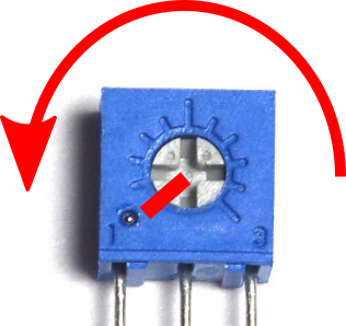
Approx.: 40 ms to approx. 5 seconds* exp. curve
trimmer max position 
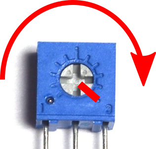
Approx. 80 ms to approx. 25 seconds* lin. curve


Be warned! This website uses cookies! Read our privacy statement here