Display mounting improvement idea

I just thought about the display mounting...
Maybe it would be easier to just use a longer pin header like this
image

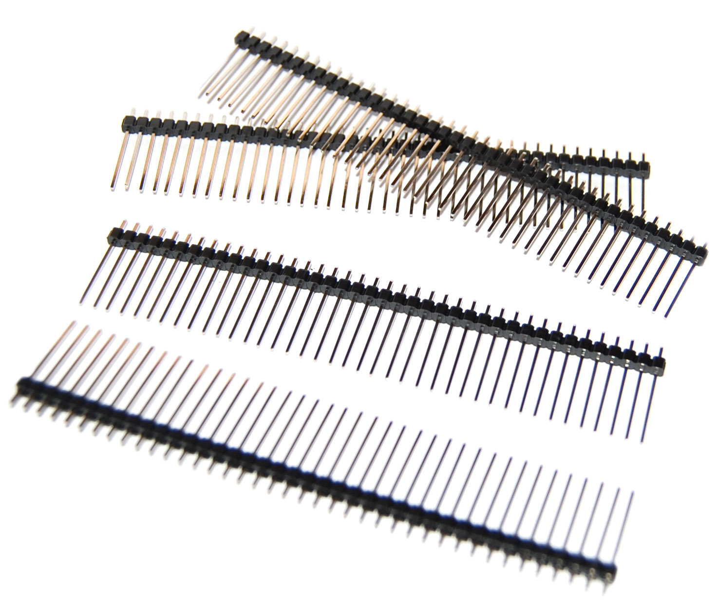
It could probably be mounted from the top of the display and there would be no need to push the black plastic thingy around, since it is long enough to be soldered like it is. you could then just cut off the excessive top.

what do you think? is this easier than with the normal, short pin array?

Comments

  • something like this
    image
  • that's a good idea.  i ended up using an 8hp blank panel to move the pins down but it was a bit sketchy.
  • I ended up melting the plastic pretty bad so I removed all the pins and soldered them in one by one. ~X(
  • yeah. on the first connectors I got the plasticthingy was quite easy to move.
    on the 2nd batch it was quite stuck in place much more tight. :-/
    I'll see if I can find the longer part.
  • edited January 2014
    i sometimes  move the plastic thing a bit up and down before soldering to loosen it.

    after soldering it on one side i remove the plastic and then solder the other side. this way i am able to cut the individual pins in case i have to desolder it.

    this way its also possible to push the plastic clother to the ends of the individual pins before soldering so that they barely stick out of the pcb. this way i don't need to cut them after soldering, but still have tiny solder joints that are not in the way of other components. (like with the midi jacks on the lxr)
  • I liked the way that the PreenFM2 mounts the lcd, it does so with some turned socket pins much like the IC sockets, and has a male one soldered to the screen.

    This way, you just insert the screen to the female socket on the pcb, with the added benefit that the lcd can be removed in the future without any soldering.

    You can check it out in the preenfm2 building instructions.
  • nice idea with the female header.
    Is it sturdy enough?
    I'm just not sure there is enough space between the display and the PCB on the LXR since an angled display won't fit here.
  • edited January 2014
    I like the way the PreenFM2 mounts its LCD - it's great that they can be removed easily, and also it angles the LCD toward the user, so it's easier to see while you're using it.  I've started mounting most of my LCDs that way, but I generally don't use cases for my stuff, so I don't have to worry about fitting the LCD into a case.

    I don't think there's enough room in the LXR case to mount the LCD that way, unless you got a really well fitting low profile header/socket combination...  I'd be a bit worried about how good the connections would be in a low profile socket, but it might work.

    On the PreenFM2, there are screw holes at the bottom of the LCD - I ran a zip tie through the bottom holes, and it's very secure.  There are screw holes on the LXR too, you could mount the LCD with screws and it would be totally secure.
  • any other source for those turned low profile headers than sparkfun or ebay?

    i didn't find them at mouser nor reichelt when sourcing for preenfm2
  • How about asking Xavier, the PreenFM´s creator for a source?

    He might even have some ideas for the screen mounting.

    He could be reached at his website or over at MI forums
  • I'm about to give a go at building the LXR with beginner-to-intermediate soldering experience. 

    Couple of questions. First, why not solder the display connector before mounting the MIDI ports?

    How is the display mounted/secured to the PCB? It's not immediately clear in the instructions. Do you solder the pins to the display? 

    > Make sure to cut off the legs of all the parts below as short as possible, so that the display sits flat on the PCB. Then solder the display to the connector from the top.

    Should I shield these connections by putting electrical tape over them? 

    Anyone have any recommendations on a fool-proof way to complete this step? It's the only one I'm apprehensive about (let me know if there's other stuff a beginner should look out for!) 
  • I shielded them with electricians tape, just to be sure. Believe me unsoldering the LCD is a challenge, even for pros...
  • edited January 2014
    It's not a bad idea to put a layer of electrical tape on the board below your lcd - I've had lcd feet short out connections on some devices (not on the LXR though).  Definitely trim all the connections on the top of the board below the LCD as short as you can after soldering.  I don't have tape on my LXR and it's fine, but it's not a bad idea to use tape.

    Yes, you solder the LCD pins to the display and to the board.  You can't easily remove it after it's soldered on.

    You should solder the MIDI ports first because once the LCD is on you won't have access to the top of the board under the LCD.  All connections that have to be made to the board under the LCD should be soldered before you put the LCD on - you won't easily be able to access those connections after the LCD is on. 
  • strstr
    edited January 2014
    You should solder the MIDI ports first because once the LCD is on you won't have access to the top of the board under the LCD.  All connections that have to be made to the board under the LCD should be soldered before you put the LCD on - you won't easily be able to access those connections after the LCD is on. 
    Could I not just solder the connectors, then the MIDI ports and other components under the LCD, then the LCD? Maybe it's not any easier. 
  • It's been a while since I built mine...  But I think the solder pads for the LCD connector are on the top of the board anyway, so soldering them from the bottom might not work all that well.

    Soldering on the MIDI ports first makes sure that the LCD connector doesn't stick out the bottom too much - if you did it the other way around you might make it so your midi connectors don't fit quite right.  It's not hard to solder the LCD connector in from the top.
Sign In or Register to comment.